General Utility Shaders /**/
Light Surface
Shader Functionality and Parameters
The
mia_light_surface shader is primarily intended to help creating physically plausible renders of the "visible" portion of a light source - the actual tube in a fluorescent tube, the actual bulb in a light bulb, etc. while still using a traditional CG "light" to create the illumination of the scene (see the use cases described below).
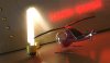
An example of using
mia_light_surface
In the image above, actual illumination comes from a long thin rectangular area light, which is set not to cause any specular highlights. The visible "glow" of the fluorescent tube is set be visible in reflections (and hence become our much more accurate "highlight") but still be invisible to FG rays, so it will not be incorrectly picked up as additional light.
The
mia_light_surface shader can either provide a color all by itself, or derive the color from an existing (set of) light(s) in the scene.
The shader itself only returns a color and does not do any
other shading per se. A tip is to use it plugged into the
additional_color of
mia_material.
These are the parameters of the
mia_light_surface shader:
declare shader "mia_light_surface" ( color "color" default 1 1 1, scalar "intensity" default 1.0, scalar "fg_contrib" default 0.0, scalar "refl_contrib" default 0.0, boolean "use_lights", scalar "lights_multiplier" default 1.0, vector "lights_eval_point" default 0.0 0.0 0.0, array light "lights" ) version 3 apply texture end declare
color is the overall color, and applies both to built in light or light derived from light sources.
intensity is the intensity of the "built in" light, i.e. the surface will appear to the camera to have an intensity of
color multiplied by
intensity (assuming
use_lights is off - see below).
fg_contrib is how much of the light that is visible to FG rays, and
refl_contrib how much that is visible to reflection rays.
When
use_lights is on, the lights listed in the
lights array are polled and their intensity (multiplied by the
lights_multiplier) is
added to the output dictated by the
intensity parameter; i.e. if L is the output of all lights in the
lights list, the final output color of the shader is:
color * (L * lights_multiplier + intensity)
When
lights_eval_point is 0,0,0 the intensity of the light is evaluated (with shadows disabled) at the point in 3D space that is being shaded. Since this may vary in an undesirable way for a light that has an IES profile, one can specify an explicit point at which the light color is evaluated. This point is in the coordinate space of
the light.
Use Cases
Illumination in General
In the real world every light emitting object is visible, has an area, and emits light from that area. When using FG,
mental ray will treat any surface that adds light energy into the scene as if it was a light source. However, to get the best possible quality out of this, one need very high FG settings, with long render times.
Light sources in computer graphics can be either point sources or area lights, and the area lights themselves may, or may not, be visible in the rendering. In most cases It is simply more efficient to use actual light sources:
Emitting FG, Not emitting FG, And using a point light
The image above shows 3 patches that are all using the
mia_light_surface above a checkered plane. The leftmost patch has it's
fg_contrib set to 1.0 (and is hence illuminating the floor), the other two has it set to 0.0. But the rightmost patch has a point light hidden behind it.
At close distances (or with very large light sources, like the entire outdoor sky) FG can illuminate objects just fine with very good quality. At long distances or with small sources, using an explicit light source is much more efficient.
mia_light_surface gives separate control if the object should be "seen" by reflection rays or FG rays (and how much) via the
fg_contrib and
refl_contrib parameters. This image uses a slightly reflective checkered plane to illustrate this. No light sources are used behind these patches:
Visibility to FG and reflections
The leftmost patch is visible both to FG (illuminates the plane) and reflection (reflects in the floor). The center patch does not illuminate (
fg_contrib is zero) and the rightmost does not reflect (
refl_contrib is zero).
Highlights vs. Reflections
In the real world, the visible light emitting objects are both visible to any camera photographing the scene, as well as reflect (glossily) in other objects. In computer graphics, light sources tend to be invisible to the camera, and their reflections are "cheated" with the help of "highlights" by material shaders.
The
mia_material supports a protocol for light sources to tell it if they should generate highlights or not. This is implemented by most OEM applications light sources, look for flags like "Affect Specular" or "Emit Specular" or similar on the lights.
Light hidden behind patch with various flags.
There is a light hidden behind each of the patches in the image above. The leftmost is emitting both specular- and diffuse light. The middle one is only emitting specular light, and the rightmost is only emitting diffuse light. Furthermore, the rightmost patch has it's
fg_contrib set to zero.
As we can see, the leftmost patch creates too much illumination, since we get illumination both from the light and from the patch. The center patch generates the strange effect of a small "highlight" (our light source is just a point light) inside the reflection of what we are trying to sell as "the visible light".
In this case this effect is distracting, so we want it disabled - like we have done on the light on the right. That is the way to go; let the surface handle the reflection, not the illumination, and let the light handle the illumination, not the reflection (i.e. no traditional "specular highlight").
An alternative, when using area lights, is to allow the area light to create the specular highlights:
Area light specular highlights can also "work"
This illustrates the alternative. The leftmost patch again uses a point light with specular on. This is what we do
not want, since it looks strange. The other two patches use an area light. The middle patch has the area lights specularity turned off and the patch has
refl_contrib set to 1.0, the right has the lights specular enabled, and a
refl_contrib of zero.
As we can see, both variants on the right side "work", so it is a matter of choice which method is used for area lights.
However, the middle method tends to be preferred, because often one is using a geometrically simple area light (sphere, rectangle, etc.) in place of an
object that is actually geometrically complex (a neon sign, for example). In those cases one
definitely want to use the method in which the object is reflected, and the light does
not emit specular light:
Complex geometry require real reflections
Both neon signs use a rectangular area light for their illumination, and both cast nice area shadows (as witnessed by the small spheres). But the sign on the left has a blatantly rectangular "reflection", which does not make any sense. For this use, definitely use the method on the right side, with the lights specularity off, and the surface's
refl_contrib nonzero.
Complex Light Distribution
In a real world luminaire, complex interactions between the bulb, the reflector, and various occluders determine the final distribution of light flying off into the scene.
Naturally, one do not want to consider all those minute details just to make a rendering of a desk lamp, and indeed, the problem comes pre-solved in the form of measured data (i.e. IES or EULUMDAT files).
The
mia_light_surface shader can get its intensity from a light. This saves the user the time of keeping the intensity and color of the "visible surface" in sync with the intensity and color of the light source. If the
use_lights is on and some light is passed in the
lights parameter, this happens automatically.
This works fine for isotropic point lights and similar, but when using measured light data, one can run into an issue:
Picking up intensity/color from the lights
The above scene contains three spheres. Lets assume they are the models of the light bulbs of some desk lamp. They each contain a light that has an IES profile fitting that
luminaire applied.
The leftmost sphere uses
mia_light_surface with a manual setting, i.e.
use_lights is off. The user is responsible for making sure the intensity and color of the surface is "correct", as well as manually keeping it in sync with any animated intensity changes etc.
The center sphere uses
use_lights, but we get a very strange effect from it; half our lightbulb is dark. This is because the IES profile we chose only emits light in the down direction. Since the light source is in the center of the sphere, only the lower half of the sphere will gather any intensity values off the light!
Clearly this is not desirable; the IES profile is a compound effect applying to the
entire luminaire, and should not be "painted" onto the light bulb itself!
The solution is to use
lights_eval_point as is done on the rightmost sphere. Here a point just in front of the light is picked (in the lights own coordinate space) as the "evaluation point". Each point on the sphere (regardless of its location) will have the intensity "measured" at that point in space.
This gives the sphere a color that automatically follows any intensity- and color-changes of the light, yet is uniform across the surface of the sphere. This sphere will reflect correctly in a more plausible way than a traditional "highlight" would.
In conclusion: The
mia_light_surface shader allows...
- ...creating a surface as a "stand in" for an existing light, that "looks" bright, without emitting additional light into the scene.
- ...controlling the amount of reflection and light actually introduced into the scene.
- ...driving the appearance of the surface from an existing light source.
- ...more physically correct "highlights" by replacing them with glossy reflections of actual high-intensity objects.
Another example using
mia_light_surface